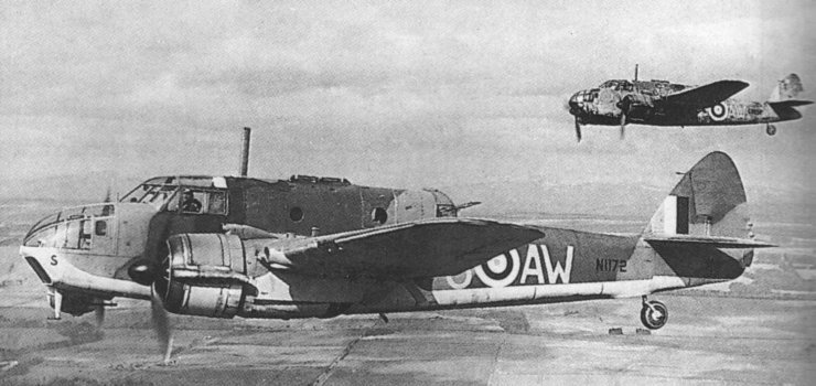
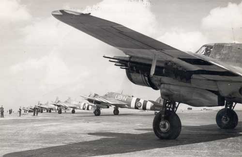
Heavily armed , the Coastal Command Beaufighters constituted one fo the most feared anti-ships weapon for the Kriegmarine.
The Bristol 156 know after as the Beaufighter, was born from an improvisation imposed to the Bristol study board, then directed by Roy Fedden & Leslie Frise. When came the Munich crisis in 1938, the R.A.F. had desesperatly a lack of modern fighters, & particularly heavily armed aircraft, usable for long distance escort & night fighting.
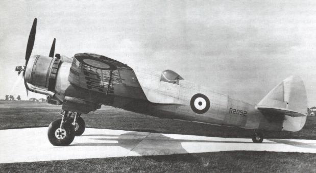
Bristol put a final touch to the anti-ships bomber Beaufort, when the directors thought of using some major parts of this aircraft for a new long action range fighter. The Bristol Type 156 project relied on the use of exterior fuselage elements & landing gear of theType 152. Specifications demanded the use of the new star shaped motor Bristol Hercules. The was only to create a new plane cell. The 1st project, realised in few days, was submitted to the Air Ministry in october 1938. 4 prototypes were ordered, the 1st one took off on july 17 1939, only 45 days befor United kingdom was at war.
The Beaufighter 1st combat, was at the end of the Battle of Britain, in its Mk 1 F version , dotated of the AI Mk IV radar. When the Blitz against Britain ended, the 5 squadrons of Beaufighters had won over 60 air victories.
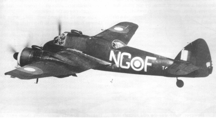
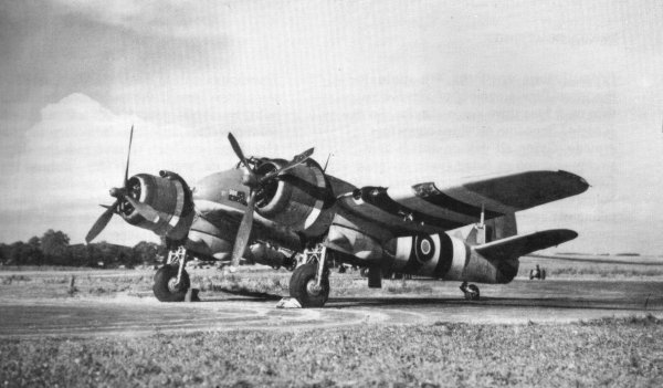
On the Coastal Command chief initiative, an English with a truely French name, the Air Chief Marshal, Sir Philip Joubert de la Ferté, were constituted mixed units, including the Beaufighter as fighter, fighter bomber, & torpedo aircraft. The first group so constituted included squadrons 149, 236, & 254, based at North Coates, Lincolnshire. Soon , the Coastal Command units had been engaged versus the german convoy circulating under protection of ships heavily armed against the allied surface ships as well as against their aircrafts. While the fighters Beaufighters kept busy the ennemy aircrafts, the bombers covered up the torpedo aircraft attack. The units were reinforced in may 1943, by Mk VI C Beaufighters armed with 8 rocket launchers fixed under the aircraft wings. This Beaufighter version was unofficialy named "Flakbeau" while the torpedo aircraft were named "Torbeau". 2 more wings of the same type were constituted, composed of Squadrons 144, 235, 404 (Canadian), 455 (Australian) et 489 (New-Zelander). Directly derivated from the Mk VIC, the Mk X Beaufighter became the main run version, almost exclusivly used by the Coastal Command. It was propulsed by Bristol Hercules Mk XII & could carry the same exterior charges as its predecessor in the ganune. Some Vickers .303 machine guns were replaced by Browning's, sometimes twinned. While - the Coastal Command Beaufighters continued to harass the german ships who tried to force the blocus on the Atlantic harbours, in the Gulf of Gascony, the attack Wings of Beau MkX were deployed in Scotland at the beginning of 1944, to organize patrols, designated "Rovers", to intercept the ships trying to supply the Tirpitz, refugied in a Norwegian fjord, & come back loaded of iron ore vital to sustain the german war efforts. Until december 1943, the 455 Squadron (R.A.A.F) based at Leuchars flied on Handley Page Hampden, accomplishing anti-ships mission in the North Sea. By this time, it was retired from operations to convert it on Beaufighter. On april 2 1944, it joined the 489 Squadron (R.N.Z.A.F.) commanded by the Wing Commander J.S. Dinsdale, on the base of Langham, Norfolk. Where they formed the Langham Strike Wing. The specialty of this Squadron was anti - Flak fight, opening the way for the 489 Torbeaus. In this role, the 455 was the 1st under ennemy fire, but with the Wing Commander J.N. Davenport, assisted by Squadron Leaders Collin Milson & A.L. Wîggs, the unit had, according to many official historians, 3 of the more combative & well inspired tacticians of the Coastal Command ships fighters. During the Normandy landings, 8 Squadrons from the Coastal Connnand were dotated of Beaufighters. It was the 143, 144, 235, 236, 254, 404, 455, & 489, most of them had been transferred to airfields in the south of England to prevent any ship sailing on the Channel.
Many 1:48 Beaufighter model kits exist - or have existed- , 2 vacuformed version by Falcon, & a resin Beaufighter Mk VI realised by José Femandes. This last one, is difficult, not to say impossible to find.
I don't want to bother you about what's inside the box, you could have read it as many times as many aircraft model kits magazines exist, so there is no interest in that, & a little daunting when it's the eighth time. If i had a very positive first impression, going further in the investigations, i discovered how long this aircraft will take to become a good beaufighter. Clearly, the model is far from what could be read here or there, particularly on the windows, landing gears, engines & interior.
After fifteen minutes of ecstasy, i told myself it would be welcome to find all the documentation i have on this aircraft, beginning by the MAP map. The wings are true to the map, the only little difference is on the formation's lights (those which stay white, & not red, nor green...) that does not mean that the Tamiya kit is false. The differents panels of the intrados, as well as the extrados are well represented, except for the rescue boat's access panel between which is on the left wing, between the end of the engine's spindle & the wing's root. The access to the tanks & their gauges have not been forgotten. The landing gear's hatch are particularly nice, the holds are well designed, which will avoid some delicate maskings for painting. Regarding the fuselage, there is to note an error, & a regret. The error comes at the rear part of the aircraft, the curve between the tail and the tail wheel is too strongly marked. The regret, is that the tailfin have not been designed to be removable without playing with blade. If the stabilizers ( particularly the shape of the mobile areas ) are not true to the plan, i discovered many photos confirming that the cuting chosen by Tamiya is correct. The fuselage's engraving is fine.
After this "Walk Around" of the aircraft, let's come to the critics of the interior & engines. In this sector, Tamiya stay equal to itself, this means rubbish.
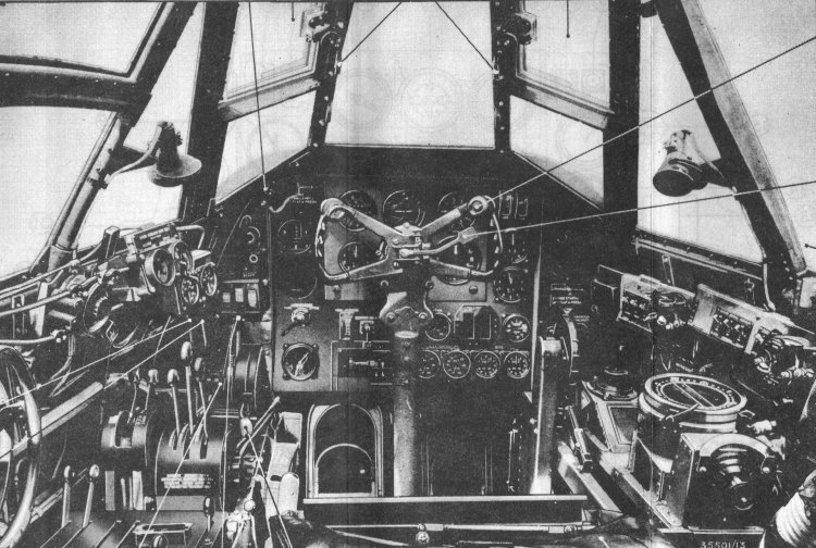
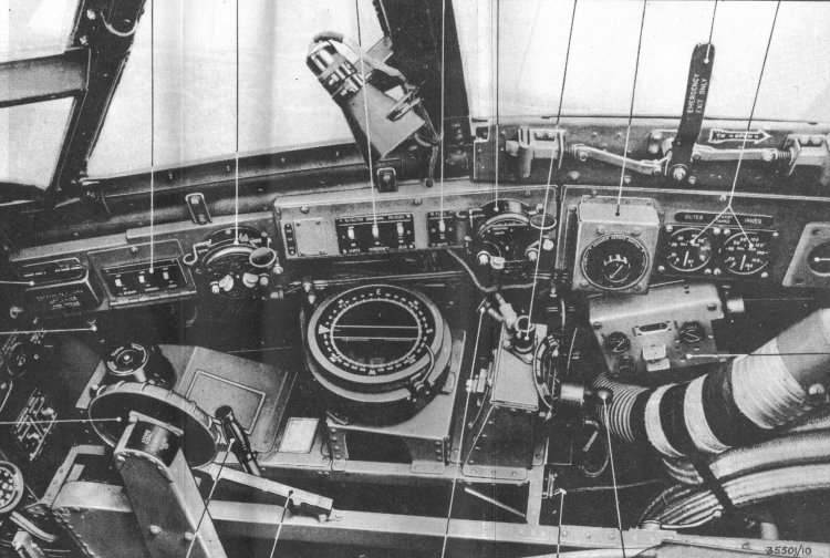
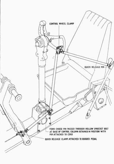
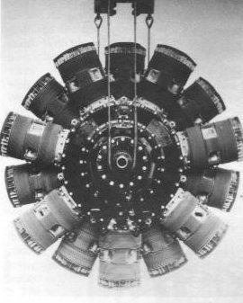
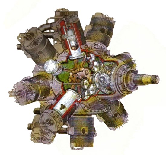
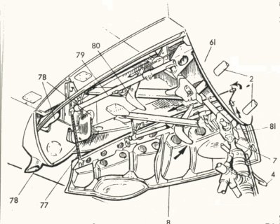
The interior is unhappily, as the other japanese productions, & will need to be entirely remade. The instrument panel is representeed by a decal, the consoles are flat & with no living aspect, & the 2 seats would deserve to be replaced. The belts are represented by decals, which is far of being the idea of the century. The engines were highly disappointing. The cylinders of the Bristol Hercules are rough, & Tamiya have totally forgotten the exhaust pipes which connect to the annular collector. Only consolation concerning this aircraft's area, the engines hood are great & the the propellers marvelous. The windows are also disappointing & have something like a magnifying glass effect ! I will not keep the landing light & the "clears" representing the formation's lights. The Beaufighter interior : Deciding to represent the rear post open, the 1st step consisted in cutting the opening of the rear post, before rebuilt all the elements of structure applied to the aircraft's sides. This operation will give a true relief to the aircraft's interior. The instrument panel, to the english standards, is not a difficult part. I worked as usual with aluminium sheet, ( the ideal is a Offset printing sheet) cut to the instrument panel's shape, & drilled at the instruments locations. The central panel, rectangularly shaped is realised separately, to respect the relief it had regarding the rest of the instrument panel. The Beaufighter's pilot manual identify precisely each instrument of the aircraft, which allow you to drill accurately, according to the Waldron's "British Aircrafts Instruments" panel. After the drilling, the painting & a light sheen, each instrument is cut & glued to its place with a drop of white glue, remountable in case of error. Once insured of the position, you let it dry, & fix each instrument with a drop of Cristal Clear. TheTrim wheel, located at the right side of the cockpit, comes from a "Reheat Model" set. Warning, the Trim wheel could be located either to the right or to the left of the column, always depending of the aircraft's origin. Think about it, and compare by the Serial Number where the aircraft you've chosen to built came from. The side panels are sanded and entirely remade, accordingly to the pilot's manual schemes. The photo-etched gears comes from the same "Reheat Models" set as the Trim wheel, the compass is turned on a lathe in a grape piece, painted & sheened, then agremented with a panel from a Waldron set, cut with Punch & Die. The heating pipe is rebuilt with a telephone wire on which i rolled a thinner cupper wire, & the numerous wires running on each side of the side panels are represented by cupper wires of different diameters. The control column given this the model kit is particularly nice, it will be conserved in that state, without forgetting to put in a position according to the position of the modile areas. The pilot seat has been remade in plastic card, without forgetting the rabatment system. The whole thing as been painted in dark olive, "weathered" with Rub'n Buff to obtain an operationnal sheen.
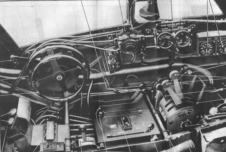
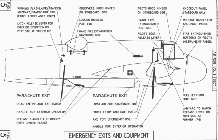
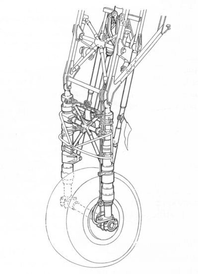
Then, belts will be made in lead sheets with Waldron buckles. 2 lights & a visor will be made & kept until the preparation of the front canopy. The rudder bar is superb, it will only be positionned accordingly to the tailfin. As for the pilot, the observator seat is rebuilt in plasticard, treated & painted the same way. Having decided to represent the bubble open, i will have to realise all the structure elements surrounding the opening in scratch. A plumber gauge helpt me to create a precise print of the front & rear frames located on the structure lines around the opening. These 2 frames were fixed to the floor & only took there locations during the fuselage assembling. The floor & the seat support are really nice, they will not have to be modified. You will not forget to represent the emergency equipments, refering to the pilot's manual which give you a complete list. Tamiya got the good idea to represent the oxygen & drinkable water carboys, but infortunately, the piece given is just a frame. After having lenghtened the floor, a shelf had been remade in plastic card & plastic shafts (Evergreen), & a carboy turned on a lathe in a grape of plastic. It will be remoulded in resin. The shelf's structure has been painted in dark green, the carboys in yellow. The differents cutaways i had, note holes located in the front & in the rear of the 2 aircraft's inferior access hatchs. These holes are not represented on the model kit. So you will have to remove the 2 uprights front & rear holes, & replace them by a plasticard plate drilled with 6 holes. The 2 central access hatchs are painted & sheened, but will only be fixed during the final operations, accordingly to the assembling map, which note 2 hatchs closing by 2 towing wires. The rear hatch could also be actionned by hydraulic jack, particularly on the aircrafts produced by Rootes. Last fitting before the fuselage assembling, the cannon's holes have to be drilled in order to receive after the painting operation, a metal pipe to represent the 20mm cannon. The closing of the fuselage causes no problem, it perfectly joint & the aircraft will not eat many putty. The inferior part of the aircraft strengthened the all set & give the right dihedron for the wings, excellent idea. Warning, the structure line appeared on the glueing joint level, on the front part of the fuselage is strictly fictive, you will have to make it disappear by any usual means. The windshield given by Tamiya, is way too thick. It will be thermoformed, as well as the rear bubble. I decided to use the bubble given in the Falcon kit, which is exemplary crystal clear. 2 lights were fixed to the front windshield stiles, as for the opening system & the ejection of the right panel which could served as emergency exit. I did not assemble the cal .303 7,7mm machine gune, but keep it for the diorama. The fuselage is nice and does not require much exterior work. A plasticard strip will be glued in the front of the observator bubble, & 2 streamlined body, bubble shaped will be add under this bubble, on the left side & under the framework, on the right side. The stabilizers gears are remoulded "from the block". You will have to rebuild 'guignols' in stretched plastic, & positionned them according to the serial number of the aircraft, in extrados, as for the aircraft i've chosen, or in intrados. The antenna will only be fixed after the final assembling, just before the painting. If you decide to assemble the Beaufighter without changing something at the engines level, the assembling will be particularly easy. When i realised this model, no accessorist had yet been interested in the Beaufighter. A friend realise for me a crankcase & a cylinder i only had to remould. But you can now find magnific 1:48 Hercules engines. An opening is realised in the left engine hood, giving a direct sight on the opened engine. At this time i've painted the exhaust collector, with a paint composed of black & cupper, turning to yellow on the collector's lips level ( magic of the increasing temperatures). 1 of the trickiest (& repetive) step is the setting up of the exhaust pipes, converging to the annular collector which is well represented on the model. These pipes are made in telephone wires (again) painted in marroon & elded with oil painting in order to represent the varied colors that a pipe can have, depending on the temperature. I needed calm to center correctly the resin engine on the piece supporting the cooling flaps (flaps which i also decided to modifiate). The lighting wires as well as the fuel shafts are added to the engine before it take his place under the hood ( phew, it enter without scraping). The cooling flaps given in the model are in close poisition. Guess what, i prefer the flaps open ! The 1st step consist to remove the original flaps from the engine hood. Then new flaps are made in plastic already rounded, coming from coffee plastic cups, the strips positionned outside the flaps are made in plasticard ( Evergreen 0.010 x 0,020 ). The model is particularly well designed, a the engine block can be positionned correctly despite the removing of the flaps coronna. The exhaust exits given in the model are useless, i chosen the White-Metal pieces from the Falcon kit. They will only be added after the painting. Last point, you will not forget to represeny by Evergreen strips (Diam 0.025), the 4 fixation point which maintained the annular collector to the crankcase. Once the engines finished, the wings will not ask for much work. The assembling is clean, not really putty eater. Tamiya have well represented the ailerons. I only made a cut to their edge. The landing lights will be replaced by 1:43 car lights, & a wall frame will be made between the 2 lights. The orignal glass fit perfectly to its location. The front part of the position lights is replaced by a piece of color ruler. This is the only way to show the mass effect of the lights. The rear part of the lights stay colorless, the original pieces will be used. The main landing gear, although finely engrave look a little gauche. So you will have to remove the shaft uprising at the exterior of each strut, & replace them by a piece of needle of the same lenght. This allow to let light go through the interstices of pieces of thin diameter, & lighten considerabily all the set. The wheels given in the model are ugly, only the rim will be kept, & added to Mosquito wheels fromTrue Details, which have a flatten aspect.
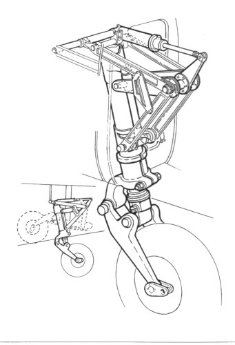
The hold & the landing gear hatchs are really nice. They can be assembled, painted & elded before taking place in their location.
The rear wheel is interdependant to its strut, & does not have an anti skid groove. So i've remoulded the rear wheel of a Mosquito & substituted it to the Tamiya's.
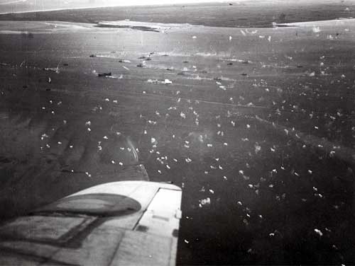
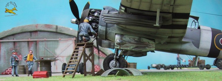
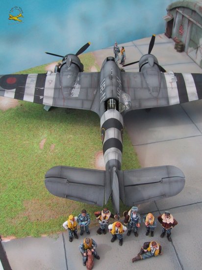
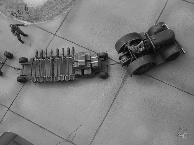
Aircraft flying within the Costal Command, the plane i decided to assemble was painted in Dark Sea Grey on the upper parts, & in Sky type S, down. The leading edges of the wings as well as the scratches area have been covered with RubN'Buff, then the aircraft has been painted in Humbrol Dark Sea Grey. Some panels have been lighten to render the different colors of a paint which have suffered of the marine climate. The paint has then been peeled on the fragile zones, then the invasion stripes have been applied on the wings & fuselage. Be careful to peel weel the paint before painting the black & white stripes, because the aircraft have not waited june 6 1944 to be at war & be damaged. Some lighter peelings are represented on the stripes. All the markings are stencil or hand made ( excepted the serial number made with transfers ), a New-Zeland flag is applied to the left front side of the aircraft. It is at that time that the exhaust pitps, the landing gears & propellers are taking their place. The exhaust trails are represented by a fine airbrushed line, the oil & fuel streaks appears around the filling & control holes. They are realised with ... oil paint. The Den Helder attack: 3 Beaufighter units took parts in the Den Helder attack, each having a specific role in the operation. Add to their onboard weaponery, the Sqn 455 Beaufighters were armed with rockets. So i decided to represent the rockets on their trolley, after assembling. You have to remove the rockets from their rails, rebuilt the sliding launcher by applying 2 stripes ( Evergreen Diam 0.025 inch) on each side of the rail. This is the only change to give to the kit Tamiya's rails. In no way, the rockets ignition wires will not be fixed to the rails, because they were firstly fixed to the rockets, then connected to a plug located at the rear of the rail. During Overlord's prelude, most of the Coastal Command units have been moved to the south of Britain. On september 24 1944, while they had all came back to their bases, 14 aicrafts from 143 Squadron were called to Langham where they met Squadrons 455 & 489 (Torbeaus) to attack the ships anchored in Den Helder (Holland). For this attack, Mustang fighter bombers played the role of escort & anti-Flak fighter. Their duties were divided this way: 143 Sqn attacks of the port's infrastructures 455 Sqn attacks of ships/Flak 489 Sqn attacks with torpedoes The choice of september 25 coincide with the withdrawal of the allied troops involved in the Operation Market Garden in Arnhem, which let us think that this assault is part of a diversion to ease the rescue of the airborne troops. 23 ships were anchored in Den Helder, & the assault force was welcome in Nieuland & Terchelling by large salvoes of light Flak, which were really accurate. A Beau dived on the ships & disintegrate, another dived at sea, approximatly 2 kilometers to Den Helder's shore. When the assault Wing left Den Helder, many ships had been damaged & a class M minesweeper sunk by the Sqn 455 Beaufighters hits. 2 Beaufighters were missing, on the mission return, including the NT 987 from 455 Squadron. The 1st step of the realisation of a dioram is the building of the basis, not too smal, nott too large ( the main subject would lost in it ). For the Beaufighter, i've chosen a square basis of 50 centimeters (20 inches) of side, representing in 1 corner, a section of hangar. The hangar structure is made with wood, the frontage with plaster reinforce by a meat safe fence. The corrugated iron's doors are scratch made : a homemade bench vice allowed me to shape a piece of cupper, which served me as a master to thermoform all the needed corrugated irons. The scene i decided to represent is a typical custom of the Royal Air Force members, a photo next to the aircraft. The figurines comes mainly from Tarmac & Elan products. Most of them were given little plastic surgery. They're oil painted (Winsor & Newton ) The David Brown tractor comes from Tarmac products, as well as the bombs lying on the trailers. The tractor & trailes are painted in Bronze Green, standard color for the Royal Air Force vehicules at the end of the war. 2 trailes conservated in the Hendon's R.A.F. Museum give a perfect example for the colors.
|
|